Creating laboratory infrastructure
«Laboratory of superconducting metamaterials» in NUST «MISiS» (December,2012)
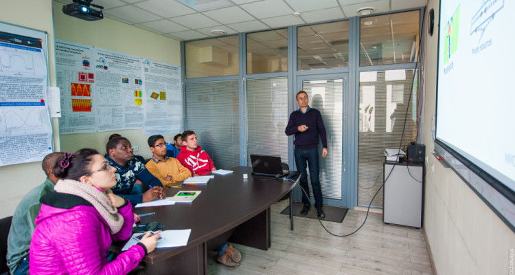
Today the Laboratory consists of two functional parts: laboratory for carrying out experimental studies using cryogenic and other process equipment, including the cleanroom (class ISO-7) to manufacture microchips, and office for seminars and meetings, as well as for working with documents and taking a break. All rooms are equipped with modern office equipment such as – personal computers to collect, store and process experimental data, the Ethernet network with Internet access and traditional whiteboards for employees to discuss and plan the details of the research process. It is a small disadvantage, that the premises are separated geographically quite far apart: laboratory is in the basement of building “B”, and office is on the seventh floor of the same building. That’s why it is planned to create some relaxation areas in the laboratory too. Such minimally adequate comfort combined with high-tech equipment is suitable for stimulating the creative process.
To date the laboratory is ready for doing research – basic equipment is installed and set up. Repair and construction work for building the infrastructure and for meeting the needs of the planned research were realized stage by stage in accordance with the plan. Each room has been technologically designed. The design of the office space was held jointly with the firm – supplier of furniture, and was made in the stylish manner with a suitable color palette for the floor and furniture. Alongside with that a thoughtful optimization of working places was done. Laboratory space was designed by the companies “MosElektronProekt” ( MOSEP, Moscow) and “IBC” Systems (Serbia) with regard to the necessary power, water and gas, as well as air conditioning. The cleanroom (class ISO -7) with the system of air control (humidity, temperature) was created for the manufacturing purposes.
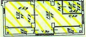
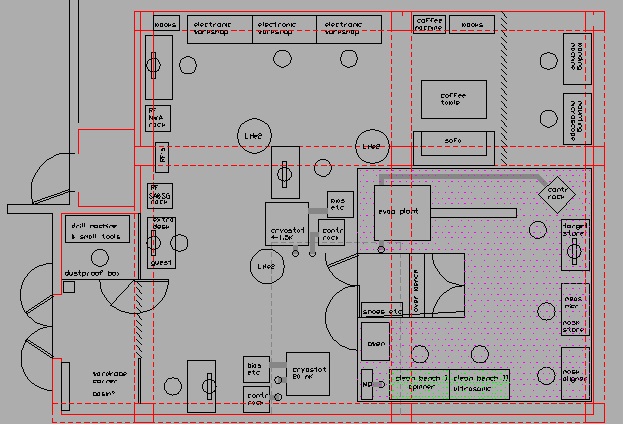
The technical plan of the office space is in Figure 1a), the plan of the laboratory space is in Figure 1b). Both of the spaces were redeveloped. The office space was divided as follows: a space for seminars and meetings for 12-15 people – recreation room, office room for 6-7 work places , the manager’s office, technical secretary`s corner. The photo of the room for seminars and talks is in Figure 3a), the photo of the technical secretary`s corner is in Figure 2b), the photo of the head office after repair is in Figure 3c). In the meeting room, there are two small adjacent rooms, pantry and a kitchenette, as shown in Figure 4b), where employees can have a cup of coffee or tea, or warm up food. They can also have snacks at the table in the seminar room.
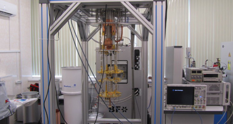
The laboratory facilities before they had been repaired are shown in Figure 5a) , and the reconstruction plan by using the clean room technology based on wall panels for is in Figure 5b). Technical room in the basement shown in Figure 6. Air handling system is an essential part of the laboratory, its installation and the general plan are shown in Figure 7. The perspective views on the experimental setup and stands ready to be used in experimental studies (already running) are shown in Figures 8 and 9.
Figure 1 – Technical plans of the laboratory premises:
a) plan of the office space B-702,
b) plan of the laboratory room B-025.
Figure 2 – The office:
a) before carrying out the repairs,
b) reconstruction plan of the office space. Right-hand side – worker office.
Figure 3 – The office:
a) seminar room,
b) technical secretary`s corner,
c) the manager’s office.
Figure 4 – The office:
a) view from the office entrance, meeting (seminar) room (on the left), main office space (on the right),
b) room, adjacent to the seminar room – kitchenette.
Figure 5 – Laboratory:
a) before the repair,
b) plan of the laboratory premises reconstruction using wall panels – cleanroom technology.
Figure 6 – Basement utility room under the floor of the room B-025, providing low noise operation of:
a) the compressor for the cryostat and compressed air systems,
b) uninterrupted power supply.
Figure 7 – Laboratory:
a) view from the street – installation of the air handling system,
b) fragment of the design documentation for the cleanroom air system.
Figure 8 – Laboratory space:
а) view of the stand with the microscope installed (on the right – one of the windows of the clean room),
b) view of the entrance to the laboratory room: on the left are the low-temperature cryostat and front windows of the clean room (behind it), on the right is the entrance of the cleanroom (class ISO 7).
Figure 9 – Laboratory:
a) a general view of the wiring stand,
b) the precision microscope “Leica” for chips quality control inside the cleanroom (class ISO 7).


